MAPBOARD DISPLAY CONTROL SYSTEMS
Distributed Multiplexer System which lets a supervisory computer operate a dynamic Mapboard with thousands of signaling lights and numeric displays.
Mapboard Display Control Systems Inc.
103 Springbrook Rd.
Port Jervis, NY 12771
Tel: 845-697-4129
Email: sales@mapboarddisplaycontrolsystems.com
The Mapboard Display Control System makes it possible for one or more remote supervisory computers to operate thousands of signaling lights and numeric displays, with a minimum of installation wiring at the Mapboard and a minimum of software within the supervisory computer. It is particularly suited to Mapboard displays in dispatching centers of Electric, Gas, Water and Pipeline utilities, traffic centers of Railways and Subways, as well as control rooms of Chemical and Manufacturing plants.
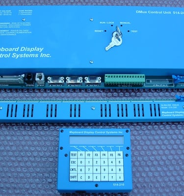
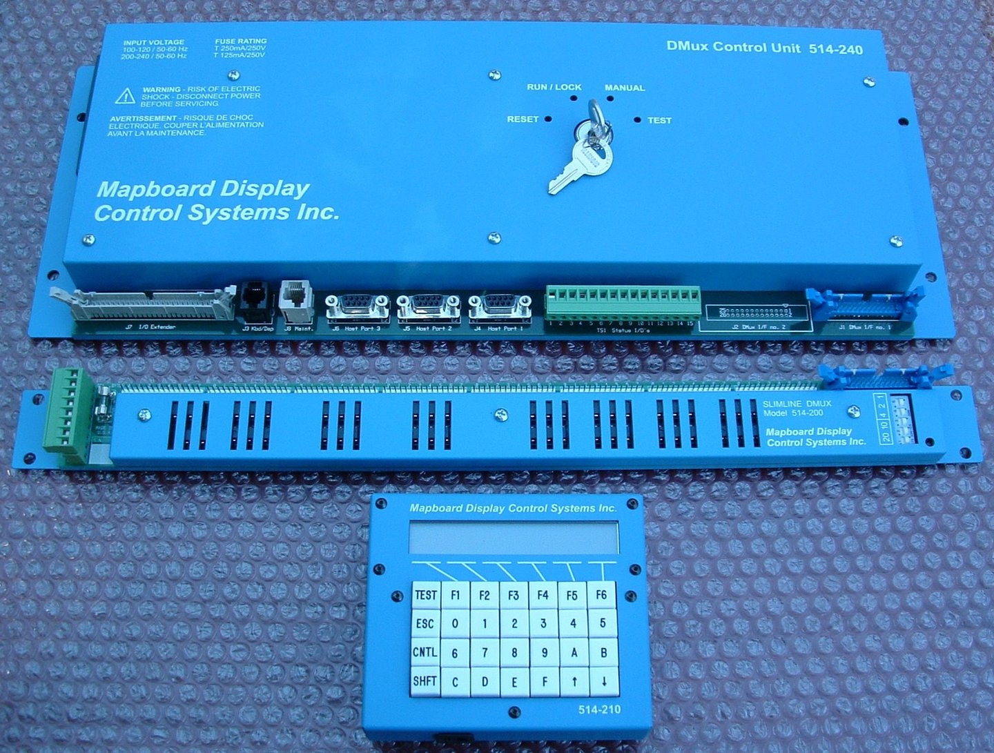
The DMux Control Unit (DCU) connects to one or two supervisory computers accepting their commands to control the status of lamps and numeric displays on the Mapboard. Each lamp can be commanded to be OFF, or ON, or BLINK (quickly), or FLASH (slowly), or DIM, or MODULATE (whereby light intensity goes up and down, creating a visually effective depiction of line or unit overload).
The DCU controls up to 2 bus lines each with up to 32 DMux Boards, each of which operates 64 signaling points for a total of 4,096 points (a multiplexed version operates up to 16,384 points). Each standard DMux point operates either LED or incandescent lamps drawing up to 0.1A at up to 28v DC. Special DMux Boards operate high power DC or AC lamps or groups of lamps, drawing up to 10A at 28v DC or 220v AC. A DCU software option lets DMux boards operate many numeric BCD Displays. DMux Boards are designed to minimize the wiring runs from lamp and display modules and make interconnection easy.
DCU also operates a serial RS485 bus line normally used to connect serial numeric BCD Displays. It operates all common serial numeric displays and through an adapter all other numeric displays. Again, this minimizes wiring and makes changing or moving displays easy.
DCU incorporates a unique automatic Lamp Test Module. On command, the DCU freezes the display for 1/30 sec and during this instant, switches a selected lamp. The Lamp Test Module checks that the current drawn by lamps changes thereby verifying that the selected lamp is not burned out. This works with both LED's and incandescent bulbs and requires no extra wiring. The test can be initiated by and results reported to, either of the supervisory computers, or Maintenance PC station or the Keyboard Display.
DCU accepts commands concurrently from two supervisory computers, a manual Keyboard/Display and a Maintenance PC station. Communication is via serial RS232 lines in an ASCII based protocol at 9,600 or 19,200 baud. Via the optional parallel interfaces, supervisory computers can issue commands even faster.
The supervisory computer can command points to be turned ON, OFF, BLINK (quickly), FLASH (slowly), DIM or MODULATE. Special commands let one operate all lamps (to visually test) or defined groups of lamps, or to do a lamp test on any one or a succession of lamps and report results. Special commands let one operate numeric displays through the DMux Boards or through the RS485 serial bus. All lamp states, including BLINK, FLASH, DIM and MODULATE are implemented with only two wires leading to each lamp; no extra wiring is needed. At the same time, the supervisory computer commands the state of a lamp, such as BLINK, without having to turn it ON and OFF periodically. DCU has a battery sustained memory so it retains and resets the Mapboard after a power failure and can even inform the supervisory computer of what the Mapboard shows.
The DCU has proven to be robustly insensitive to power and environmental conditions. It is economical to install, efficient to operate and easy to maintain.
STANDARD FEATURES
The Mapboard Display Control System is a microprocessor based assembly of electronics for the operation of a large number of incandescent lamps or LEDs within a mosaic or other type of large display board. The state of each display point is maintained by the system until changed via its manually operated keyboard or by a supervisory computer. The system incorporates all necessary lamp drivers, memory, control logic and communication logic. A basic system is equipt with the following standard features:
Control of up to 2048 individual display points each capable of driving up to 100 milliamps from up to 28 VDC.
Each of the display points can be in one of the following states:
- OFF
- ON
- FLASH (1.0 sec OFF, 1.0 sec ON)
- BLINK (0.25 sec OFF, 0.25 sec ON)
- DIM (50% Intensity)
- MODULATE (Modulating Intensity, 0%, 25%, 50%, 75%, and 100%)
Display point status can be examined or updated via a remote Keyboard/Display (Manual Operation) or via any one of three serial asynchronous RS232C interfaces (Run/Lock Operation).
Visual Lamp Test - All points can be turned ON for a visual check without affecting normal status.
Monitoring of up to four +5 volt logic power supplies and four lamp power supplies.
Power Fail Recovery - Following a power failure display conditions are reconstructed as they were before power went out. Data retention exceeds ten years.
OPTIONAL FEATURES
The Mapboard Display Control System also provides the capability of adding a wide variety of hardware and software options which further enhance the flexibility of the system as follows:
Expansion to control up to 4095 individual display points.
Expansion to control up to 16,384 individual display points (without DIM and MODULATE features).
Optional output drive capabilities.
- 50 VDC at 600 milliamps
- 240 VAC at 100 milliamps
- Current limited outputs with short-circuit protection
Automatic Lamp Test - All display lamps, LED's, and drive electronics can be tested automatically.
Control of serial or parallel driven BCD Numeric Displays.
Update of display board status via single or dual port parallel interface.
Bi-synchronous serial communication protocol.
DMux Control Units can be operated in a redundant configuration.
SYSTEM DESCRIPTION
At the heart of the system is the DMux Control Unit (DCU) which is a microprocessor based controller. Within its RAM memory is maintained the state of each display point. Each individual point can be in one of the following states: OFF, ON, FLASH, BLINK, DIM, or MODULATE. The DCU updates every point on the display board 240 times a second thereby achieving each of the these effects.
The DCU interfaces to the display points via the Distributed Multiplexer (DMux) Output Boards. A 26 conductor ribbon cable is used to daisy-chain up to 32 DMux boards and connect them to the DCU. Each DMux output board has 64 drivers thus allowing control of up to 2048 output points on a single ribbon cable. The ribbon cable can be up to 500 feet long with proper termination. The DCU can be expanded to control up to eight such cables.
Different model DMux output boards are available with various output drive capabilities. Each DMux board has a 5 position dip switch which selects a unique address for each board on the bus. In 2048 or 4095 point systems the DCU updates the output latches on up to 64 DMux boards 240 times a second. In 16,384 point systems up to 256 DMux boards are refreshed 4 times a second.
Display lamps or LEDs connect via twisted wire pairs to 64 connectors on the DMux output board. An alternate scheme allows connecting of dual points via 32 connectors using 3 conductor wire. The lamp power supply voltage is connected to the DMux output via a single terminal block and is internally distributed on the board to all output connectors.
The DMux output boards require +5 volts DC power for their operation. This power is bused from one or more power supplies to a terminal block on the DMux board. The number of logic power supplies used depends on the size of the system and the distribution of the DMux boards. Voltage sense leads from each DMux logic power supply (up to four) are brought to the DCU where they are monitored for possible outage. Similarly, dry relay contacts brought from each lamp power supply (up to four) are sensed by the DCU. The wiring must be such that the contact is closed when the power supply is operational and opens when it fails.
The DCU accepts commands from a remote keyboard/display or from one or more supervisory computers (via serial or parallel interfaces). The commands are for the changing the state of any or all display points, that is for placing a point into OFF, ON, FLASHING, BLINKING, DIMMED or MODULATING state. Thus the supervisory computer needs only to command when a display point changes state and not for every flash or blink of a point. The DCU can also be commanded to return the current status of a display point (as kept in its memory). In addition the DCU can be commanded to return the current system status showing the state of the DCU software, DCU hardware, and system power supplies.
The DCU has "operating" and "test" modes as selected by the front panel key switch. The key switch positions operate as follows:
RESET Computer is reset and all display points are OFF.
RUN/LOCK Control of display points is via host interface.
MANUAL Control of display points is via Keyboard/Display.
TEST Diagnostic and configuration mode.
A remote keyboard/display is provided with the DCU for MANUAL mode and TEST mode operation. The keyboard consists of a set of hexadecimal keys, 6 function keys, and 6 control keys. The display is a 2 line by 24 character LCD alphanumeric display. In MANUAL mode all display points can be controlled via the keyboard/display. In TEST mode all diagnostics and utility programs are controlled via the keyboard/display. The keyboard/display unit is designed for either table-top or hand-held use. It is connected to the DCU via standard modular telephone connectors and cable. This cable can be up to 200 feet long which allows the unit to be operated within the entire perimeter of the display board.
Three RS232C serial interfaces are an integral part of the DCU. Each interface is configurable via the keyboard/display for baud rate, data bits, parity, or stop bits. In RUN/LOCK mode the interfaces allow a supervisory computer to control the display points. Connection to the interfaces is via 9 pin female "D" connectors configured for DTE operation.
An I/O extender connector is provided with the DCU to allow expanding the number of control interfaces of the DCU. A DMux bus expansion module is available which provides eight DMux bus connectors for controlling up to 16,384 points. The DIM and MODULATE functions will not operate with this module. A parallel interface expansion module is also available which provides up to two 16 bit full duplex parallel interfaces.
A power fail option is offered which incorporates battery backed RAM memories which have a data retention capability which exceeds ten years. With this option installed, the DCU will retain point status during a power failure.
Above principles of operation were first designed into a Mapboard Control System in 1976 by Computer Inquiry Systems Inc. (CIS). Later, the business was taken over and expanded by Beckman Instruments and EL-CAT Inc., to where some 500 such systems operate throughout the world. In 2006, Mapboard Display Control Systems Inc. (MDCS). purchased the product line which is managed by some of the original designers from CIS. MDCS is focused on Display Control Systems and maintains the same high standards of quality and service, while introducing it to an expanded range of applications.
MAPBOARD DISPLAY CONTROL SYSTEMS
PARTIAL LIST OF REFERENCE SITES
ALABAMA ELECTRIC COOPERATIVE, INC.
ALLEGHENY POWER SYSTEM
AMERICAN ELECTRIC POWER CORPORATION
BONNEVILLE POWER ADMINISTRATION
CENTRAL HUDSON GAS & ELECTRIC
CITY OF GARLAND
COMMONWEALTH ELECTRIC
CON EDISON
DELMARVA POWER CORPORATION
EAST KENTUCKY POWER
FLORIDA POWER & LIGHT COMPANY
FLORIDA POWER CORPORATION
GULF STATE UTILITIES COMPANY
HOUSTON LIGHTING & POWER COMPANY
JERSEY CENTRAL POWER & LIGHT
KANSAS GAS AND ELECTRIC
LONG ISLAND LIGHTING COMPANY
MANITOBA HYDRO
METROPOLITAN EDISON COMPANY
NEW ENGLAND POWER/REMVEC
NEW ENGLAND POWER EXCHANGE
NIAGARA MOHAWK POWER CORPORATION
NORTHERN STATES POWER COMPANY
ONTARIO HYDRO
ORANGE & ROCKLAND UTILITIES
OTTER TAIL POWER COMPANY
PUBLIC SERVICE CO. OF COLORADO
PUERTO RICO ELECTRIC POWER AUTHORITY
SALT RIVER PROJECT - POB
SAN DIEGO GAS & ELECTRIC
SIERRA PACIFIC POWER
TAMPA ELECTRIC
TRISTATE GENERATION & TRANSMISSION
UNION ELECTRIC COMPANY
UTAH POWER AND LIGHT
VIRGINIA POWER
WESTERN AREA POWER ADMINISTRATION
For further information please contact :
Mapboard Display Control Systems Inc.
Tel: 1-845-697-4129
Microprocessor-based control for large display boards.
Maintain state with manual or computer control.
Incorporates drivers, memory, and communication logic.


Innovative Display Control Solutions
At Mapboard Display Control Systems, we specialize in advanced microprocessor-based technology for managing large display boards, ensuring reliable operation of incandescent lamps and LEDs with seamless control and communication.
Display Control Solutions
Advanced systems for managing large display boards with precision and reliability.
Custom Display Management
Tailored solutions for effective control of your display systems and lighting.
Reliable Lamp Drivers
High-quality drivers for incandescent lamps and LEDs in large display applications.
Integrated Control Logic
Comprehensive control logic for seamless operation of your display systems.
Display Systems
Explore our innovative control systems for large display boards.